Figure 1
Final Iteration
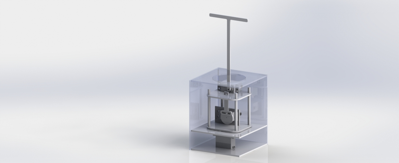
In this iteration, the MDF platforms supporting the servos are now round instead of square, and have holes cut through them to allow the servo cables to pass through to the arduino, which will be at ground-level. The Heave motion is supported with three aluminum rods that pass through nylon spacers in the upper platform, creating fewer moving parts and fewer failure points. Additionally, the tubes are attached to the bottom plate in a way that does not interfere with the support plate. They run through additional nylon spacers to ensure the tubes are square with the platform and each other, and are kept from moving up and down by music wire inserted through a hole below the platform and another above the spacer.
Next, the scotch yoke assembly is made out of laser-cut delrin, reducing the friction between the faces as the servo turns the wheel.
The upper servo is mounted in an MDF support, and the lower platform is supported by an MDF sheet. This allows the bottom servo to only exert a torsional force, and not compensate for cross forces.
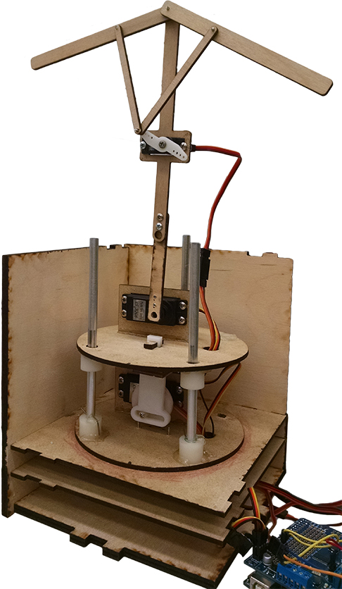
The mechanism that causes the penguin's wings to flap is seen in Figure 1. A micro-servo drives an ornithopter linkage that causes the wings to flap. After iteration 2, we felt that we had adequate time and resources to compensate for the dropped degree of freedom by adding a flapping motion. This motion will give the robot a higher degree of character and interactivity, as well as more variety in its motions.
Iteration 2
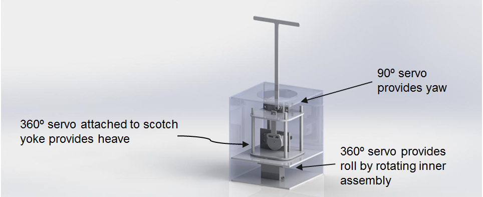
Taking what we learned from Iteration 1, we completely redesigned our mechanisms. For this iteration, we also decided to drop a degree of freedom, deciding that Pitch was not an important enough motion for our dancing robot, especially with time constraints. This iteration is made of MDF and brass and aluminum tubes.
This iteration has three servos: one at the bottom providing Roll by rotating the entire upper assembly, one in the middle driving a scotch yoke to provide Heave, and one at the top providing Yaw.
Once again, this iteration taught us a lot about how to improve the design. For starters, the brass and aluminum tubes used to guide and support the Heave motion did not slide as smoothly as desired, so we decided to abandon the telescoping aspect for the next iteration, and instead use nylon spacers and a single aluminum tube. Secondly, the holes to hold the tubes were too close to the edge of the MDF platforms, causing the corners to split and the integrity of the design to be compromised. To address this in the next iteration, we made the platforms a bit larger and the hole pattern smaller.
Next, the base holding the bottom servo was not intended for this project, but was handily available from a lab earlier in the semester. Therefore, the center of rotation of the bottom servo was not centered on the platform, leading to instability. Also, the square piece of MDF with the large circle in the center that is not doing anything was intended to support the lower platform, minimizing cross-forces on the bottom servo, allowing the maximum power and torque to go into the rotational motion desired. However, this was not implemented due to the base and the protrusion of the rods below the surface of the MDF platform. The base for the next iteration was designed for the purpose of this project and is much more stable and integratable with the support.
We decided to make the wheel and yoke of the scotch yoke assembly out of delrin to reduce friction, as these surfaces slide together.
Finally, the upper servo, merely taped to the platform in this iteration, was mounted in an MDF support in the final iteration to provide stability.
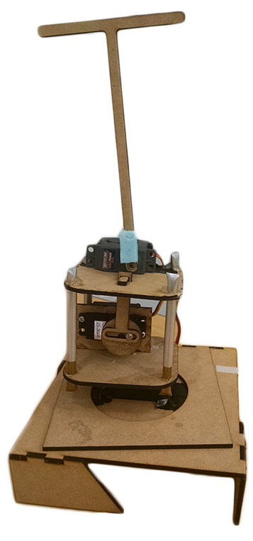
Figure 2
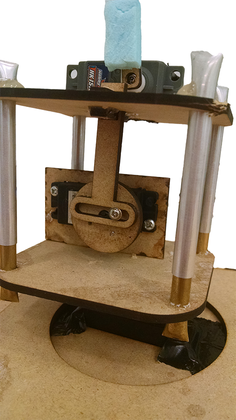
Figure 3
Mechanical Model
Iteration 1
This purpose of this iteration was to explore the potential of different mechanisms. This iteration was made of cardboard (and duct tape) and contained two servos (not in the picture) that were held in the small rectangular piece seen in Figure 5 and in a similar part that can't be seen. The vision for this iteration was to have four degrees of freedom: Pitch, Roll, Yaw, and Heave. Only the mechanisms for Pitch, Yaw and Heave are included in this model.
The hook seen in Figure 4 was intended to be connected to the head of the robot internally in some way in order to provide Pitch, however due to this iteration we were able to determine that this mechanism would not work for our purposes. Additionally, the circle seen in Figure 5 is part of a crank slider assembly to provide Yaw (primarily) and Heave (consequentially). We decided to abandon both mechanisms for our next iteration.
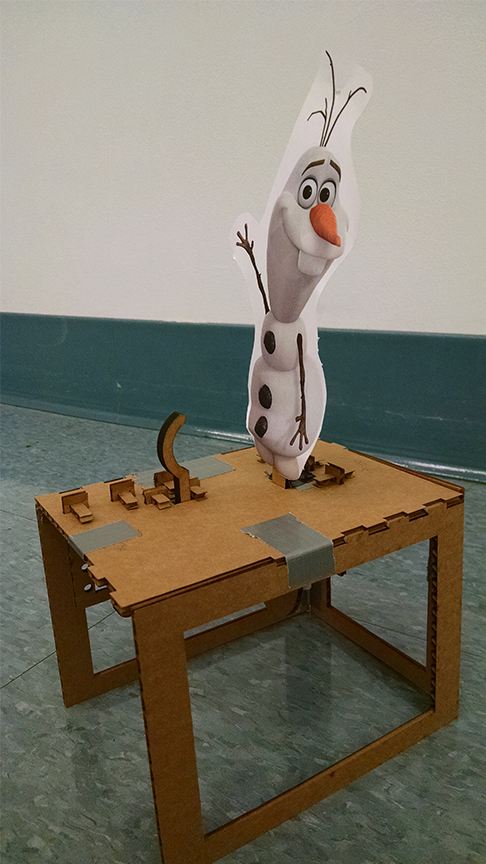
Figure 4
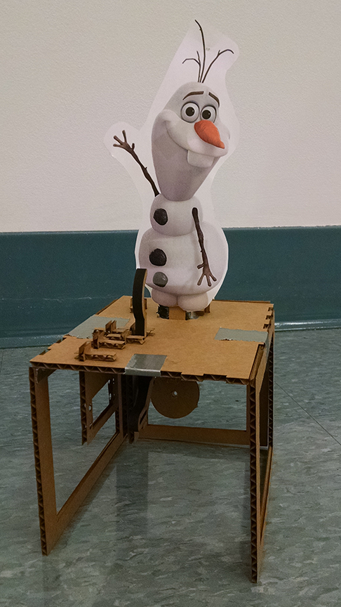
Figure 5
Sketches
Our initial sketch model (unfortunately disposed of before we thought to take a picture of it) was a cardboard box with the flaps cut off and rectangular sections cut out of each side. The bottom of the box became the top, and in this face we cut a small rectangular hole with two slits coming off of two sides of the hole. A stick of cardboard went through this hole, and we stretched two rubber bands through the slit to the bottom of the stick. This allowed the stick to bob up and down, demonstrating Heave, one of our four desired degrees of freedom. Next, we attached three pieces of thread to the bottom of the stick, such that one would pull the stick left-right (yaw), another would pull it forward-back (pitch) and a third would rotate it (roll), rounding out the four degrees of freedom. We used virtually nothing from this model in our first iteration, but it did a good job of demonstrating our desired motions.


